Ray Karadayi's paper discusses innovations in machine tool in-process measurement, emphasizing metrology close loops for high precision and cost-efficient manufacturing. It covers the integration of CAD-based measurement software with machine tool controllers, enabling CMM-style measurement capabilities directly within the manufacturing process.
Ray Karadayi
Applied Automation Technologies, Inc.
1688 Star Batt, Rochester Hills, MI, 48309 USA
Phone: 248-340-6934
ray.k@aat3d.com
Abstract
Innovations in Machine Tool In-Process Measurement and Feedback with Metrology Close Loop.
In recent years, in process measurement of parts with complicated geometrical features became necessary to manufacture at high precision and lower costs. By using CAD based measurement software developed by AAT with virtual machine modeling for programming and a real time interface with a machine tool controller, it is possible to achieve CMM style measurement capability directly within the manufacturing process. Whilst offline programming allows development of a measurement program directly from a CAD model for any GDT reporting; post processing enables to execute this program on any machine tool with ease of use like CAM programs. With this innovation in machine tool in-process measurement, an inner loop of Metrology Feedback is created to use metrology as a part of achieving highest quality while keeping cost at the minimum during the manufacturing cycle. The overall system helps in many applications from large piece manufacturing process such as aerospace wing or automotive die manufacturing to automated factory control such as engine manufacturing or a high-volume production of cell phone casing.
1. IN PROCESS MEASUREMENT
As the demand to manufacture more complex parts with higher accuracy at lower costs is increasing, measuring parts where they are made is becoming very important and more common practice in the industry and drives innovations in machine tool in-process measurement. Just looking at the number of machine tool probes sold in the recent years is a very good indication of how important and wide use this practice is becoming, making innovations in machine tool in-process measurement extremely important. Although most of these probes are used for simple measurements, the need to perform complete metrology analysis which is typically done by using a CMM is now being performed directly on the manufacturing system.
1.1 Benefits of Innovations in Machine Tool In-process Measurement
The top four reasons why in process measurement would benefit could be listed as follows:
Part Setup: Part cutting programs are created based on an assumed work piece holding coordinate system. Especially for large parts such as the case for aerospace or large die manufacturing for automotive, this process could take a long time while the machine is in idle. Using innovations in machine tool in-process measurement with an advanced software, this could be reduced to a minimum time. For small part manufacturing and multi operation processing, precise part locations could be detected automatically. This would reduce both the setup time and the processing time as parts could be cut from optimally sized blocks.
Automation Feedback: One of the reasons for performing a metrological analysis of a manufactured part is to provide correction values to manufacturing parameters based on the deviations found from the intended dimensions. Having this capability directly on the machine tool allows to feedback this metrological data to the machine tool controller allowing an automatic adaptive manufacturing process. Since this is done directly on the same machine where the part is manufactured, it could be done several times during the manufacturing process, not just at the end of the manufacturing to fine tune the part cutting process. This also allows different machines used in a multi operation manufacturing to automatically adjust to each other.
Complete Measurement Reports: Programming and running a manufacturing machine like a CMM for in process measurement generates complete inspection reports of the parts being measured without additional effort. Especially for large part manufacturing, in some cases there may not even be an option to move the part to an external measuring machine. For mass production, just measuring a few control features would not only generate inspection reports for all the parts but also provides a statistical view of the manufacturing cycles.
Monitoring Machine Performance: Machine geometry can change during machining operation due to many reasons such as excessive loads and temperature changes. By applying an appropriate in process measurement method with a gage, the changes in machines geometry can be measured. These changes can be monitored to avoid making bad parts by and by optimally scheduling machine maintenance.
2. EVOLUTION OF PART MEASUREMENT
2.1 Open loop quality control
Ever since a need emerged to manufacture parts with precision, dimensional verification methods were developed. Initially the main goal was to check if the final product was good or bad and detect any bad parts before they are sent to a customer. The bad parts would either be scrapped or if possible repaired.

2.2 Closed loop quality control
As the need for higher quality parts at larger volumes grew, the use of dimensional measuring equipment (DME) such as coordinate measuring machines (CMM) or dedicated gages became a standard in most manufacturing companies. As more detailed metrological data was being obtained from these devices, this information was not just used to determine whether the final product was good or bad but more importantly it was used to correct or make adjustments to the manufacturing process and even the original design process. However, since additional equipment is used and, in most cases, specially built rooms is necessary, this process is expensive.

2.3 In process measurement
By adding a measuring probe directly on the machine tool and by using a powerful in process measurement software, it is possible to create a tighter inner loop within the manufacturing cycle. This reduces the dependence on an external measuring device and allows real time feedback to adapt the manufacturing process creating true innovations in machine tool in-process measurement.

3. MEASUREMENT UNCERTANTY
In order to provide a sound in process measurement system, all the sources of measurement errors that are caused by the system and measurement methods are studied and software algorithms and processes are developed to minimize the overall measurement uncertainty. The final measurement errors are a function of the errors from the measurement process and the errors of the actual manufacturing process:
Er = Es + Em (1)
Where
Er: Total error detected
Es: Errors caused by system (probe, machine, workpiece)
Em: Actual Manufacturing process errors.
We want to accurately detect the errors caused by the manufacturing process itself. In order to achieve that, we must first remove or minimize the Es to be within the allowed uncertainty budget.
The measurement errors caused by the system can be attributed to 3 different sources.
Es = Ep + Eg + Ew (2)
Where
Ep: Errors caused by the probing system
Eg: Errors due to changes in machine geometry
Ew: Errors due to work piece holding
• Errors of the probing system: Since this is the part of the overall system that is used only for in process, and otherwise would not be there for the manufacturing, any errors caused by directly from the probe system are studied to minimize its effect on the overall uncertainty.
• Errors due to machine geometry: The machine geometry could have variations from its intended parameters. Squareness of two axes or misalignment of a 5-axis head are common causes. Furthermore, these could change rapidly with machine loads or temperature swings. Quick calibration and compensation methods are developed to minimize its effects on the measurement results.
• Errors due to work piece holding: Assumed part locations could have deviations which will ultimately cause measurement errors. Simply using the work offsets created for the cutting process could not be trusted especially for multi operation applications. Accurately determining exact locations of the parts will minimize the total measurement errors caused by the in-process system.
4. MEASURING PROBE
Machine tool probes are designed to work in the harsh environment of the machining environment and can be loaded like a cutting tool directly from the tool magazine. In order to perform high precision metrology on a machine tool, first the probe measuring accuracy must be achieved. The measurement errors of a probe also originate from several causes. Each one of these causes has been studied and a calibration method has been developed to compensate for these errors.


Figure 6 shows the error profile of a kinematic probe with a run-out error. Using special calibration methods, these errors are detected, and calibration data is generated for the probe at the set measuring velocity. These compensation values for each contact vector of the probe with the surface of the part are used to correct individual measurements.
A calibration program is automatically generated to detect these errors by measuring a ring gage or a calibration ball as seen in Figure 7.


5. ERRORS DUE TO MACHINE GEOMETRY
Maintaining machine tool geometry is very important for manufacturing parts with high precision. Unfortunately maintaining the intended geometry of a machine is very difficult and expensive. A 3 Axis machine tool would have 21 sources of errors due to its kinematic structure. Figure 9 shows these errors

For each axis, there would be 6 causes of errors:
In addition to these, there would be 3 errors for perpendicularity of each axis to each other.
For a 5-axis machine, there would be other geometrical errors due to axes of rotations.
A 5-axis head on a machine tool may not have the rotation axis perfectly aligned to its intended direction. A 5-axis table could also be out of position. Multi axis machines would have more complexities causing other geometric errors.
Figure 10 shows some examples of these additional sources of errors.

In order to minimize the effects of the machine tool geometry errors, we apply two methods.
5.1 Monitor machine tool errors:
Machine tools are manufactured to meet its intended specifications and all the errors described above meet the allowed tolerances by either hardware adjustments or compensated by a correction table within the controller. However, since the machine geometry can change during the use of the machine tool over time, it needs to be periodically checked and calibrated. This recertification is usually done once a year and takes some time. It could be expensive because both for getting this service done and in machine downtime.For in process measurement, quick setup and calibration methods are developed. By using a measurement probe and a master gage specifically designed to measure the errors that needs to be monitored, a quick and in some cases fully automatic measurement programs can be executed to collect the change in machine’s geometry. By monitoring these changes, it is possible to predict and schedule machine recalibration ahead of time. More importantly, knowing that the machine meets its intended specifications, we have confidence in the measurements collected as any errors we see would not be due to machine tools geometry.
5.2 Apply correction for machine tool errors
Several gages are used to automatically measure the machine tool geometry errors and apply correction for them in real time. By using a suitable gage, the accuracy of the machine tool can be calculated within minutes and any discrepancy can be detected. One of the tools that is incorporated with the measurement software is a ball bar system as shown in Figure 11. This gage has 6 composite bars connecting 4 precision spheres. By measuring this gage at the 4 spheres, any geometrical shift within the machine tool is detected and recorded to monitor over time. More importantly, immediate correction values for the linear and squareness errors representing the volume of this gage can be used to apply correction with the software.

This gage could also be used to detect any deviations in the 5-axis head rotations by measuring the top sphere at different locations of the head angles. By using these measurements, a correction value is used by the CappsNC software to minimize the effects of this error.
Another gage is a simple gage with only one sphere that can be attached to a 5 axis table as seen in Figure 12. This kind of gage can be placed at any part of the table and a measuring program would measure the sphere at several different orientation of the table.

The correction is applied directly to the rotation axes of the table within the measuring software. In some cases, these values as well as the detected center of the table are automatically uploaded to the machine tool controller also allowing the cutting programs to work with the actual geometry of the table.
6. ERRORS DUE TO WORKPIECE HOLDING
Machine tool cutting programs are generated at an assumed location where the part would be held. These are usually stored as a translation value under the work offset parameter of the machine tool controller. Some controllers also have options to apply the parts orientation in terms of its rotation from the intended axes.
Any errors in holding the part precisely from the intended location would cause the machine to cut at a wrong location. If a hole is to be drilled at a location, it would be drilled at a slightly different location because the part is not exactly where it should be even though the machine was at the correct coordinates.
6.1 Extracting part from a block
Cutting out a part from a square block is a simple example of how in-correct piece holding can affect the result. The initial shape could be a block as it is the case in a lot of molding applications, or it could be a pre-cast or wrought material with a non-uniform starting shape needing to be finished. In order to make sure that this operation is performed with a good part extraction, without in process measurement the following must be considered.
Figure 13 shows the problem that could be caused by a mis-aligned work piece. As the work piece is located with a slight rotation, and especially with a little offset, it is possible that part of the cutting could be at the edge or out of the volume of the work piece.

By using in process measurement, a precise alignment of the part can be created. A program that could measure points around the block calculates the actual orientation and the center of the block. Figure 14 shows the screen where these points are used to create a work offset G56 for the alignment. During the execution of the program generated, this work offset is updated to the controller automatically.

Once the controller is updated with this new alignment, cutting program adapts the machine motion to carve out material at the actual location. This allows a much smaller starting work piece size, and very small setup time which is performed automatically by the system without the need for an operator. Figure 15 shows the measurement points and finished product.

6.2 Advanced alignment methods
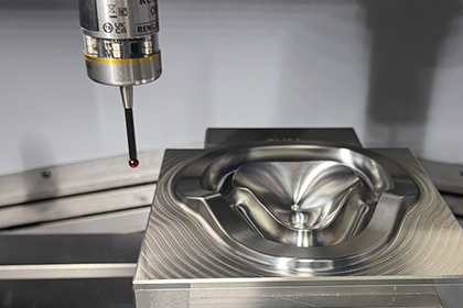
For parts with complex shapes such as non-prismatic features, the part alignment could be even more difficult without innovations in machine tool in-process measurement. Manufacturing impellers by surface finishing from a cast work piece is a good example of this.
Figure 16 shows one of these parts to be processed on a 5-axis table machine.

By using the CappsNC in process measurement software, a set of measurement points are created, and a measurement program is generated. The results of this measurement data is used to compare with the original CAD model of the part calculating profile errors. A 3D best-fit function is also introduced into the measurement program by using best-fit settings shown in Figure 17. As a result, a part coordinate system which allows the machine to process this part at the shortest time without any risk of undercutting is calculated and updated as a set of correction parameters to the machine tools controller.

The correction parameters for this kind of application are written either as an extended 6 degree of freedom work offset with part location and orientation or it could be applied as an offset to the A and C rotations of the table by bringing the part to the optimal position for the cutting process.
6.3 Manufacturing airfoils and blades
In some cases, the special shape of the part such as the airfoil of a jet engine, or a gear profile would require special mathematics and methods to manufacture this component or to repair it. In addition to calculating precise part location to help manufacturing, a special algorithm that calculates specific parameters or simulating a gaging method normally applied external to manufacturing is necessary. Innovations in machine tool in-process measurement make this possible by integrating special measurement functions and using a high-level metrology programming language DMIS.
By automatically calculating points at cross sections of the blade, the centroid, leading and trailing angles and radius, and locations of special gaging points are calculated by the measuring software. Having these parameters automatically updated in the controller allows the cutting program to adapt to the actual condition of the part.
When repairing a blade or gear, the reverse engineering method is applied. A probing program that can adaptively digitize a shape or a curve measuring program is executed creating a CAD entity representing the actual profile. This profile is then exported into a CAD file in Iges or Step formats automatically from which a CAM program creates a new cutting path that repairs the part without damaging it.
6.4 Manufacturing of large parts
Manufacturing large parts such as an automotive die requires special in process methods. To have these kinds of parts measured on an external measuring device would be very expensive and sometimes not practical at all. Parts may have to be moved back and forth multiple times to measure and apply corrections based on these measurements. Figure 18 shows an example of such repair process.

The unique measurement method this process requires is the ability to manually move the machine to locations where the desired features will be measured. For example, the four-hole locations are initially not at a known location to be able to run an automatic probing program. However, using CappsNC software, a specialized macro is quickly generated to allow the user to bring the machine above each hole and start an automatic measuring cycle. The calculated images of these features are automatically displayed on the software screen and by using them an exact alignment is calculated. This alignment is later uploaded to the controller to allow the machine to perform the cutting process correctly.
Similarly, curve profiles or surface measurement macros can also be generated and executed at the desired locations. The collected measurements in this case are immediately compared to the CAD solid model and a measurement report is generated.
6.5 Large non-rigid part manufacturing
When manufacturing very large parts such as composite structures or a wing of an aircraft, it could be very difficult to hold the part within the intended location. Furthermore, because of the size of the part, just with its own weight or with clamping, it could take a slightly different shape.
Figure 19 shows an example of wing trim and drill operation.

The goal is to adapt the cutting or drilling program to precisely follow the shape which the part takes. Since this shape will be different for each part, a probing program is generated from the CappsNC software to measure its profiles. Any numbers of coordinate systems along the length of the part or sections in consideration are generated. This data is then used by a special program called, AAT-NCFIT to adapt the cutting program to follow the exact shape.
A screen of the NCFIT is seen in Figure 20.

Several in process measuring programs can be developed and stored in the machine tool controller for optimizing tool compensation. These programs at the different phases of the cutting process are started automatically and corrections are uploaded to the controller in real time for the next cutting operation to adapt to the changes of the tool shape. This in process method is especially used in large volume mold manufacturing such as cell phone mold manufacturing.
7.2 Deflection of part under cutting forces
In some applications, part itself can change its shape under forces applied during the cutting process. This could be the case when manufacturing parts with thin walls such as airfoils. One important application where in process measurement helped with CappsNC software is manufacturing high precision parts on a turning application. In this case an automatic measurement program is used to measure the profile errors of the part just before final finishing cut. These errors are used to automatically update the
machine’s pitch correction table and part is cut again with these new corrections active. This way, the part errors measured by the in-process system are used as a direct feedback to the machining process correcting the effects of the forces on the part.
Figure 23 shows an example of this process.

7.3 Thermal compensation
Another important cause of manufacturing error is the thermal expansion of both the part and the machine. The changes in the temperature could be very unpredictable and the effects on the system are non-linear. One method of correction for the thermal expansion is by applying a compensation method directly into the in process measuring software. Figure 24 shows the configuration screen for in process thermal compensation for both the part and machine.

Although this method of compensation for the thermal expansion is quite effective for the measurement results, this by itself does not really help the manufacturing process as the correction is applied only on the measurement software. For this reason, an in-process method is adapted to directly measure the effects of the thermal expansion and correct it for the manufacturing process itself. This method is especially helpful when the effects of thermal expansion is nonlinear, i.e., for a turning application, most of the expansion is on the location of the turning table and not the machine actual axis itself. By measuring this shift with the aid of a simple gage, the active work offset is calculated and corrected hence allowing the machining program to adapt to this thermal change.
8. SPECIAL APPLICATIONS
In process measurement is applied in many special applications to both help with manufacturing process and to generate measurement and metrology reports without taking the part off from the machine tool. Two of these applications are mentioned below.
8.1 Measurement of aerospace part on an 8-axis robot
Aircraft structures are manufactured by a supplier of Boeing using an 8 axes machine with a robot. There are many hole locations at different orientations being drilled. Incorrect positioning of these features causes a lengthy approval process to repair and is very expensive even if they could be saved from scrap. By using an in-process measurement strategy, both part locations are calculated and hole locations before and after drilling are measured. CappsNC software has a virtual machine modeling (VMM) feature where a true simulation of the complete machine is possible. Geometric measurement paths are created automatically with optimum tool orientation to align the probe with the hole axis. Automatic collision avoidance also allows a very fast and safe program generation. Figure 25 shows the CappsNC screen for this application.

8.2 Manufacturing high precision cutting tools
A manufacturer of high precision cutting tools is interested in using in process measurement to assure that the end-product achieves the intended cutting envelope. The actual frame of the cutting tool and the pockets where the actual cutting bits would be planted are manufactured by using 5 axis machine tools. By using the CapsNC software, an in-process measurement strategy is developed to measure the cutting tool pockets. From these measurements and by using the nominal dimensions of the cutting bits, the actual cutting envelope is calculated and compared to the desired envelope. The deviations are reported as a measurement report and applied to the cutting process as correction.

9. IN PROCESS METROLOGY
In addition to using in process measurement for the purpose of helping the manufacturing system, it could also be used as a metrology device allowing to use the machine tool very similar to a coordinate measuring machine (CMM). It has been shown up to now that by applying the algorithms and methods developed within the CappsNC software, the measurements collected on the machine tool can be trusted. By programming the machine from a CAD model, any type of features can be measured with any number of points. For example, a cone with multiple points can be measured and both its form and angle can be reported. A surface profile can be measured by quickly developing a program that measures many points at different vectors. Through innovations in machine tool in-process measurement, measured features can be referred to create true position call outs at different settings.

10. CONCLUSIONS
Throughout this paper, we showed that in-process measurement is a very important part of sustainable manufacturing strategy. By using a measuring probe and metrology software with the ability to directly connect and interface with the manufacturing system, it is possible to make complex measurements on any type of part and machine tool.
The most important benefit of in process metrology is enhancing the manufacturing process in a number of ways by reducing the effects of various errors on the manufacturing quality. Advanced measurement analysis reports are used as a correction hence achieving ‘closed loop metrology feedback’ within the manufacturing cycle. It has been demonstrated that this method can be applied on very complex parts manufactured on multi axis machine tools and robots.
The benefits of innovations in machine tool in-process measurement is seen not only on large parts where it is a must to use as moving the part to a CMM would be very expensive or just impossible but also on small parts high volume manufacturing by automating the measurement process within the manufacturing cycle.
Complete measurement reports with metrological analysis can also be generated without additional effort making the in-process measurement a very powerful tool for sustainable manufacturing. New innovations in machine tool in-process measurements are now being applied by many leading manufacturing companies from aerospace and automotive applications to cell phone mold applications.